|
It seems
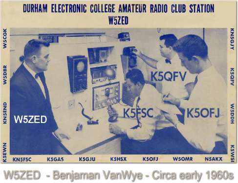
like so long ago in the 1960s when I heard my first
front-to-back demonstration of a two-element, 40 meter
horizontal phased array by Van, W5ZED. I was astonished by
the 30+ dB of front-to-back from Van’s antenna, and I knew
from that moment on that I could not rest until I put up a
similar array.
I listened
intently as Van described his set of two dipole elements, 30
feet high, spaced at 28 feet.
(For the old timers reading this, Van used the Kirk
Helical-Wound elements for his dipoles. These elements used
copper tape that was helically wound on a 22 foot tapering
fiberglass tube. The 40 meter element was 44 feet
tip-to-tip, about two-thirds the size of a full size 66 foot
element.) The dipoles were fed with
electrically equal lengths of coax, terminated into a
switching arrangement that would allow him to choose
different lengths of delay line between the elements. The
switching arrangement would also allow him to swap the delay
line between the elements to reverse the direction of the
array. His dipoles ran north and south, producing a pattern
that fired east and west. Van lived in San Antonio, Texas,
and I lived in Crowley, Louisiana, due east of Van and right
down the center of his antenna pattern. In addition to an
obscene amount of front-to-back, Van consistently had one of
the strongest signals on the 40 meter band. I don’t know
who invented this particular configuration of the antenna,
but Van certainly was one of the early proponents of the
two-element phased array. Other notable phased array
experimenters that I remember from this era were Merle
Saxton, W5CNM, a broadcast antenna engineer by trade, and
Jack, W5RGP. While Van used coaxial delay lines, Merle and
Jack used variable L/C phasing networks. It did not take me
long to put away my coax delay lines and become a proponent
of the variable LC phasing network.
Van felt
that he could make significant changes in the frontal
pattern take-off angle by changing the phase relationship
between the elements. I think he believed this because of
the changes in signal strength that he could detect off the
front of the antenna as he selected different lengths of
delay line. Unfortunately, I have been unable to verify
this with my modeling of the antenna with various NEC2
antenna programs. To the best of my ability to determine
with software and on-air tests, the take-off angle and
frontal lobe of the phased array is not altered
significantly by the phase relationship between the
elements. The biggest change in take off angle I could
detect, from a wide range of phase angles, was
one-and-a-half degrees. As a result, I must conclude that
the take-off angle on the front-side of the phased array is
almost totally determined by the array’s height above
ground. The angle at which maximum front-to-back occurs,
however, is drastically affected by the phase and current
relationship of the two elements. To summarize this point,
as the phase angle between the two elements varies, the
angle at which maximum front-to-back occurs on the rear of
the pattern changes dramatically, while the frontal lobe
changes very little.
Van also
described his phased array as having a cardioid pattern in
the azimuth plane, but software generated patterns and
on-air tests with rotatable two element phased arrays are in
close agreement to a pattern virtually identical to a
parasitic yagi azimuth pattern. My guess is that Van looked
at the azimuth patterns generated by vertical arrays and
assumed that the horizontal array would be the same. For
those who are only able to put up fixed dipoles for the
phased array, don’t be too discouraged. I’m sure Van felt
the azimuth pattern was a cardioid because the antenna is a
very good performer, even 45 degrees off the main axis.
. |
|