|
Those of you who have heard me
demonstrate the 40 meter, two-element horizontal phased
array, especially under quiet winter-time conditions, have
heard the 30 to 60 db of front-to-back the array is capable
of generating. In summer-time conditions there is a lot of
static and band noise that keeps the S-Meter reading
upscale, so it is difficult to see much more than 20 db
front-to-back ratio on the S-Meter, either on receive or
transmit. Only during the quiet band conditions we have in
the winter months will the S-Meter be able to show the 40,
50, and sometimes even 60 db front-to-back demonstrations.
It seems impossible that a two-element antenna could have
this much front-to-back, but I think the plots that I have
done with NEC2 antenna modeling programs will offer some
insight as to how this could be possible.
We
typically see antenna elevation and azimuth patterns, but
these two types of patterns are only 2-dimensional slices
through the 3-dimensional pattern. Choose the wrong azimuth
angle for an elevation plot, or the wrong elevation angle
for an azimuth plot, and you will get patterns that are
totally misleading about the true antenna pattern. The best
representation of an antenna pattern is the 3-dimensional
plot that is available in several of the higher-end antenna
modeling programs. Only then will the 2-dimensional slices
at specific angles through the 3-dimensional pattern make
sense. Think of these two slices as specific days of your
entire life. You would not want anyone to judge your life
by what they observed on only two different days, would
you? Nor should you judge an antenna by a couple of
2-dimensional slices though it�s 3-dimensional pattern.
I used an
antenna-modeling program called Multi-Nec by Dan Maguire,
AC6LA, to investigate the two-element horizontal phased
array. Multi-Nec uses Excel spreadsheet macros as the front
end to various NEC2 engines. It comes bundled with a
generic NEC2 engine, but can use the engines in other
programs like EZNEC, EZNEC+, EZNEC-M Pro, EZNEC/4 Pro,
NEC-Win Plus+, NEC-Win Pro, GNEC, Antenna Model (Teri
Software), and 4nec2. Dan�s website states that �Multi-Nec
is an Excel application that can make multiple simulation
runs of an antenna while automatically changing one or more
aspects of the model between runs. Run antenna modeling
programs on autopilot�. I seriously doubt if I could have
complied all the plots and data on the phased array, as well
as other antennas I have investigated, without the Multi-Nec
concept of antenna modeling. Load up the spreadsheet and go
visit with the family while Multi-Nec does all the work. I
recommend it highly.
I often use
the brute force method of antenna modeling � let the
computer do the grunt work to make many small incremental
changes in specific antenna parameters, such as phase angle
and current ratios, and then evaluate the results by looking
at the antenna patterns, feedpoint impedances, take-off
angle, gain, front-to-back, front-to-rear, etc. After
enough iterations, it becomes apparent which changes are
beneficial and which are not. I like to design while
observing the elevation pattern, especially the backside of
the pattern, which determines the front-to-rear ratio. It
should be noted that front-to-back is only specified for an
azimuth pattern, which of course is a 2-dimensional slice
through the 3- dimensional pattern. Front-to-rear, however,
is a ratio of the forward energy versus the energy off the
back of the antenna. Front-to-rear ratio is typically a
less impressive number in decibels than the front-to-back
ratio of a single slice of the pattern.
Enough
pontificating, let�s look at some patterns and numbers. For
the two-element phased array investigated in Multi-Nec I
used #12 copper wire elements, 66 feet per element, spaced
at 22 feet, and 70 feet high over average soil. I used 150
segments per wavelength and current sources in the middle of
each element.
Figures 1
through 4 below are combination 3-dimensional pattern
plots, 2-dimensional elevation pattern plots, and
2-dimensional azimuth plots of the two-element horizontal
phased array at selected current phase relationships between
the two elements.
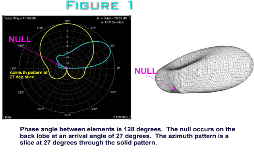
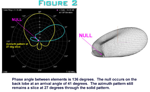
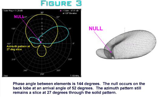
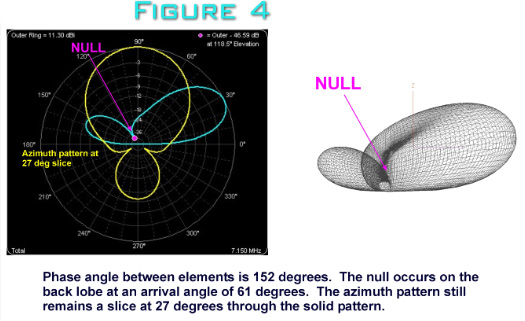
As you can
see from the above plots, as the phase relationship between
the elements vary, there are drastic changes in the rear
lobes of the pattern. The frontal lobe, however, remains
relatively unaffected by the changes in phase relationship
between the elements. As the phase relationship increases
from 128 degrees to 152 degrees, the null off the back of
the antenna changes from 27 degrees to 61 degrees. This is
how the operator can achieve maximum front-to-back in real
time as the LC network is adjusted with the back of the
antenna facing the incoming signal. If the incoming signal
has a lot of multi-path and is arriving over a wide range of
angles, the array will not exhibit as much front-to-back as
it would if the incoming signal was arriving at a narrow
range of angles.
In the real
world, of course, we don�t need high front-to-back on
incoming signals, we need high front-to-back on interfering
signals off the back side of the antenna. When working
Europe from Louisiana all this front-to-back is wasted
because there is nothing behind me but Mexico, and in the
summertime, thunderstorms in the Gulf of Mexico. The ideal
application for the phased array would be for New England
stations working Europe who would like to knock down the
rest of the United States stations by 30 � 40 db. Or, if
these New England stations were working the United States,
they could knock down the European broadcast stations by the
same 30 � 40 db. The same would apply to the Northwest
Pacific stations as they work Japan, or the West Coast
stations working into the Pacific region.
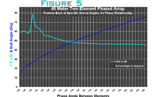
In summary, Figure 5
below illustrates front-to-back (red curve) at specific
arrival angles (yellow curve) of the incoming signal,
plotted against phase relationship between the elements.
Although the null off the back of the phased array is
greater than 45 db from signals arriving at angles of 18
degrees to 78 degrees, the maximum front-to-back (70 � 80
db) occurs at arrival angles of 27 � 30 degrees.
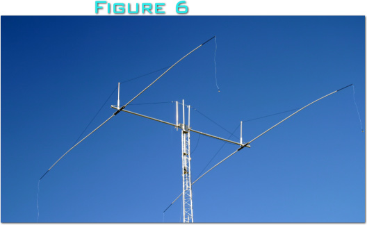
As a practical matter these
phased arrays can also be linear loaded. I use the droopy
tail method of linear loading for my array that is pictured
in Figure 6 below.
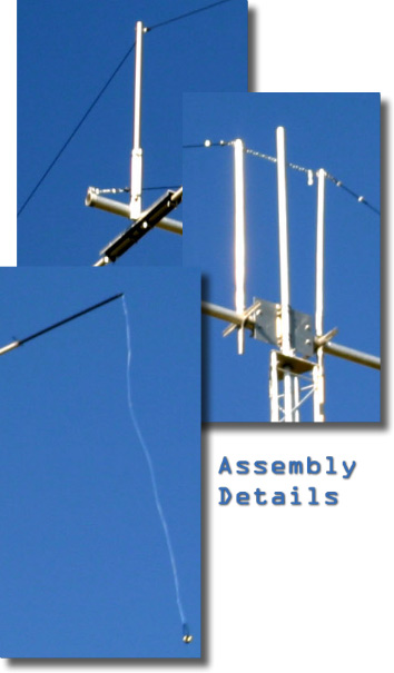
Close-up of the boom to element,
boom to mast and drooping tail.
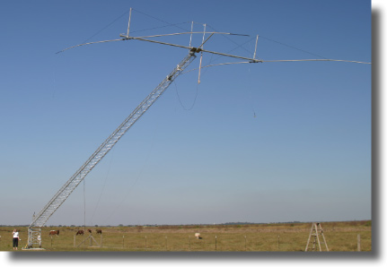
The above photograph shows
how the phased array rotates in the boom sleeve bearing
so that it maintains correct position as the tilt over
tower goes from horizontal to vertical. That's 72 feet
of tower and antenna being tilted over on a 1.25" screw
mechanism at the 4 foot level. Pretty impressive, huh?
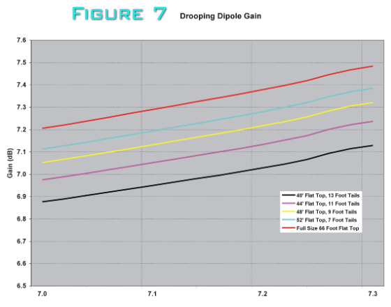
The radiating elements are made
of #13 copperweld wire running through tapered fiberglass
tubing. The tubing is 1.5 inches at the center and tapers
down to 0.5 inch at the ends. The tubing is 50 feet
end-to-end, so there is about 8 feet of wire hanging
straight down from the tips of each element, stabilized with
fishing weights or large bolts to keep them from flopping
around in the wind. This form of linear loading is the most
efficient that I tested in modeling software, being only
0.12 db down from a full-size, flat-top dipole made of the
same wire at the same height. Figure 7 below
illustrates the gain loss as a result of size reduction
using this form of linear loading. As you can see,
significant size reduction is possible with only modest loss
of performance. This method of linear loading also avoids
the problem of placing lossy coils in the high current part
of the radiating element, as well as avoiding linear loading
wires folding back on themselves in the high current part of
the radiating element.
Do not attempt to match the
elements in any way at the feedpoint. Resist the temptation
to control the SWR in either leg of the array, simply use an
antenna tuner between the LC network and the transmitter.
Depending on the phase relationships between the elements,
the resultant SWR on the transmitter side of the LC phasing
network will be about 2.5 to 1. This will not incur a
terrible amount of loss over the matched condition in good
quality coax at 7 Mhz. The only feedpoint improvement I can
recommend is ferrite beads on the outside of the coax to
eliminate currents on the coax shield, for this will reduce
the front-to-back performance of the array.
Best wishes if you decide to try
the antenna.
Charles K5UA |
|